Share this page


ISO 8583 jPOS bridge configuration
This Service Virtualization beta feature introduces support for the ISO 8583 protocol, the messaging system used for card-based electronic transactions.
ISO 8583 support
Service Virtualization supports ISO 8583 indirectly, by converting messages into XML using the standalone jPOS server, an open source implementation of the international ISO 8583 standard.
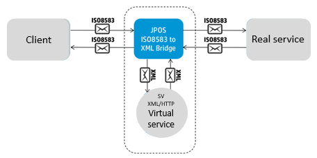
Service Virtualization provides an external extension based on jPOS that works with an XML virtual service. The Service Virtualization ISO 8583 jPOS bridge converts ISO 8583 messages into XML and passes them back and forth between jPOS and Service Virtualization.
To configure jPOS to send data to the XML virtual service, you need to edit several files which are provided by Service Virtualization. jPOS periodically scans the folder in which the configuration files are located in order to detect changes.

Before you begin
-
Prerequisite: Java 8 is required to run the SV ISO 8583 bridge.
The bridge looks for your Service Virtualization Designer or Server installation and use its Java runtime environment. If the scripts cannot find Service Virtualization and its Java, you must install Java manually and then set the JAVA_HOME environment variable to point to the Java installation folder.
- Prerequisite: Obtain and install jPOS 2.0.4. It is recommended to install jPOS on the same machine as Service Virtualization. For download and installation details, see http://www.jpos.org/.
-
On the machine where jPOS is installed, set the JPOS_HOME environment variable to the jPOS installation folder.
-
Unzip the SV ISO-8583 jPOS bridge package, located in the Service Virtualization Tools\Iso8583 folder. By default, these folders are located in:
-
Designer: C:\Program Files\Micro Focus\Service Virtualization Designer\Tools\Iso8583
-
Server: C:\Program Files\Micro Focus\Service Virtualization Server\Tools\Iso8583
-
Follow all the steps in the next sections to configure the ISO 8583 jPOS bridge.
Create a virtual service
Create and configure a new XML/HTTP service to work with the bridge.
- In the Service Virtualization Designer, create a new XML over HTTP virtual service.
- Set the virtual service to use the HTTP Gateway agent.
-
On the Service Properties page, enter the URL path for the virtual service to use as the real service URL. Configure it as follows:
http://<jPOS host>:<port>where:
host= The machine on which jPOS runs.port= The port used for the connection from Service Virtualization to jPOS. This is the port defined in the10_jetty.xmlfile, described in Configure the connection to jPOS. By default, the port number is 6001.Enter this URL into the
real-service pathproperty of the configuration file, as described in the next section, Configure jPOS. - Enter the URL of the virtual service into the the
sv-serviceproperty of the jPOS configuration file, as described in the next section.
Configure jPOS
You configure jPOS using XML files located in the deploy folder of the bridge package. To add a new virtual service to simulate the ISO 8583 protocol, you need to create and configure a new XML file and add the file to the deploy folder. Service Virtualization provides a template fo assist you in creating the jPOS configuration file.
-
In the <Service Virtualization installation folder>\Tools\Iso8583\HP.SV.Iso8583 folder\deploy folder, make a copy of 50_service_template.txt.
Note: jPOS periodically scans the deploy folder in order to detect changes, such as new files. If there is an error in the configuration file, it will generate an error and jPOS will rename the file with a .BAD extension. To prevent this:
- Do not edit the configuration file while jPOS is running.
- If you must reconfigure the configuration file while jPOS is running, create a copy of the file and save it in another location. When you finish editing, copy the file back to the deploy folder, and rename it with the .xml extension.
-
Define the TCP port on which jPOS will listen for requests from your client.
- In the jPOS configuration file for your service, enter the port value in the port property, or accept the default value of 6000.
- If you are using SSL, see Configure SSL.
-
Define communication between jPOS and your real service.
- In the host and port properties of the configuration file, define the host and port number of the real service.
-
In the
real-service pathproperty of the configuration file, define the path used by Service Virtualization to access the real service.<real-service path="/path">This is the value you entered for the real service endpoint in the new virtual service. For details, see Create a virtual service.
- If you are using SSL, see Configure SSL.
- Enter the URL of the new virtual service into the
sv-serviceproperty of the configuration file. -
Configure additional options. There are several other parameters you can modify in the configuration file to control the connection to the real service:
response-timeoutThe length of time jPOS waits for responses from the real service. reconnect-delayHow often jPOS tries to reconnect to the real service when the connection is lost. - When you are finished configuring the file, rename it with an .xml extension. Make sure the file is saved in the deploy folder.
Configure the connection to jPOS
The 10_jetty.xml file, also located in the deploy folder of the SV ISO-8583 jPOS bridge package, defines the connection to the jPOS server, and provides the interface for Service Virtualization to pass messages to jPOS. You can change the default port set in this file.
Configure SSL
There are two points at which you can configure SSL: between your client and jPOS, and between jPOS and the real service.
Listener
You configure communication to allow jPOS to receive requests from your client, by obtaining a certificate and private key which jPOS will present to the client.
-
On your jPOS machine, generate a certificate and name it the hostname of your jPOS machine. Set up the Java KeyStore containing the certificate and corresponding private key.
For example, to generate an RSA certificate and private key protected by the password
changeitusing the-keypassoption, and storing it in the filekeystore.jksprotected by the passwordchangeitusing the-storepassoption, you use the following command:keytool -genkey -alias server-alias -keyalg RSA -keypass changeit -storepass changeit -keystore keystore.jksKeytool will request that you enter the hostname of your jPOS machine. When complete, keytool will display a summary page. Make sure that CN is equal to the hostname.
For detailed instructions, refer to Oracle documentation.
-
In the jPOS configuration file for your virtual service:
- uncomment the
server-socket-factoryelement - enter the path to your KeyStore file relative to the jPOS installation folder
- enter the password for the KeyStore and private key
- uncomment the
-
You may also need to export the certificate for the client to use during the handshake, by running the following command:
keytool -export -alias server-alias -storepass changeit -file server.cer -keystore keystore.jks
Sender
To configure SSL communication between jPOS and the real service:
-
Obtain the real service's certificate and put it either in Windows certificate authority or in the Java TrustStore.
If you have a certificate in a server.cer file that was exported from the Java KeyStore, you can use Java
keytoolto create the TrustStore. It will create the filetruststore.jksprotected by the passwordchangeitand import the certificate to the TrustStore.keytool -import -v -trustcacerts -alias server-alias -file server.cer -keystore truststore.jks -storepass changeitFor full details on working with the Java KeyStore and TrustStore, refer to the Oracle documentation.
-
Configure the SSL-related elements in the jPOS configuration file.
In the
<channel>element, uncomment the following properties and set the values:-
If you have a certificate in Windows trust store, set the
winstoreproperty totrue. - If you use Java TrustStore, set its location and password.
- To disable the server certificate check completely, set the
serverauthproperty tofalse.
-
Configure logging
The logging configuration file, 00_logger.xml, is located in the deploy folder of the bridge package.
By default, logged messages are stored in q2.log in the log folder of the bridge package.
You can configure three logging elements for jPOS:
| Log filter |
|
| Console logger |
|
| File logger | Specify file location, name strategy, and log rotation. |
Filtering is based on jPOS logging methodology where each log message has two properties:
- realm - the source of the message
- tag - message type or severity
You can define filtering rules to allow or deny logging based only on tags or on realm/tag combinations.
Example:
Example: In this example of a logged message, you can see the log realm and the tag <info>.
<log realm="com.hp.sv.iso8583.log.JettyLogger" at="2015-11-05T16:44:18.575">
  <info>
    Logging initialized @1236ms
  </info>
</log>
To disable info logging for the JettyLogger realm, you can include following line in your logging configuration file:
<property name="deny" value="com.hp.sv.iso8583.log.Jetty/info"/>
In some cases, it may be helpful to log the communication between jPOS and the client , and between jPOS and the real service. To enable this, set the wiredump property in the channel element of the jPOS configuration file.
For more details, see the comments in the log file.
Configure the ISO 8583 protocol
To work with ISO 8583, you need to perform some additional configuration to describe your particular instance of the protocol. The areas that require configuration are channel, packager, and correlation.
Channel
When using the ISO 8583 protocol, messages are sent over a TCP connection from the client to the service. The protocol allows multiple requests to be sent over a single connection, and the service can respond to them in any order. Since the TCP connection is just a stream of bytes, there needs to be a way to identify individual messages. This is solved by providing the message length before each message. The stream of bytes sent, therefore, contains the sequence of <len, message> pairs.
Supported encoding
There are multiple ways of encoding the message length into the stream. jPOS provides an implementation for several of these encodings. The following table lists the encodings supported by jPOS out of the box.
| Implementation class name | Description |
|---|---|
org.jpos.iso.channel.AmexChannel
|
two bytes with length, high first, length counted |
org.jpos.iso.channel.ASCIIChannel
|
four ASCII characters with length |
org.jpos.iso.channel.BCDChannel
|
two bytes with BCD length |
org.jpos.iso.channel.CSChannel
|
two bytes with length, high first, then two zero bytes |
org.jpos.iso.channel.GICCChannel
|
two zero bytes, then two bytes with length, high first |
org.jpos.iso.channel.HEXChannel
|
four ASCII characters with length in hex |
org.jpos.iso.channel.NACChannel
|
two bytes with length, high first |
org.jpos.iso.channel.NCCChannel
|
two bytes with BCD length |
org.jpos.iso.channel.RawChannel
|
four bytes with length, high first |
To use one of the supported encodings, copy the implementation class name into the channel class attribute in the jPOS configuration file.
Custom encoding
If your channel encoding does not fall into any of the supported categories, you may need to implement it on your own.
To configure a custom encoding, extend org.jpos.iso.BaseChannel and implement the getMessageLength() and setMessageLength() methods.
To use the new class in jPOS:
- Create a folder named lib under the deploy folder of the bridge package.
-
Create a JAR file and put it into the \deploy\lib folder. jPOS will automatically load these JAR files into
classpath. -
Enter your class (my.MyChannel in the example below) in the
classattribute of thechannelelement in the jPOS configuration file.For example, the following code uses simple encoding where the first byte is the ASCII 'L' character followed by four ASCII characters with length.
Example: package my;

import java.io.IOException;

import org.jpos.iso.BaseChannel;
import org.jpos.iso.ISOException;
import org.jpos.iso.ISOUtil;

public class MyChannel extends BaseChannel {
    @Override
    protected void sendMessageLength(int len) throws IOException {
        // Some check for min and max permitted values
        if (len > 9999)
            throw new IOException ("len exceeded");
        else if (len < 0)
            throw new IOException ("invalid length");
        // First comes 'L'
        serverOut.write('L');
        // Then four ASCII characters with length  - ISOUtil.zeropad() converts int to String with specified length
        serverOut.write(ISOUtil.zeropad(len, 4).getBytes());
    }

    @Override
    protected int getMessageLength() throws IOException, ISOException {
        int l = 0;
        byte[] b = new byte[5];
        // While length is 0 keep reading - 0 means keep alive message, see in code below
        while (l == 0) {
            // Read exactly five bytes
            serverIn.readFully(b, 0, 5);
            // Make sure the start is correct - 'L'
            if (b[0] != 'L') {
                throw new ISOException("Expected 'L' at the start and not byte 0x" + Integer.toHexString(b[0]));
            }
            // Extract characters from position 1 - after 'L'
            String s = new String(b, 1, 4);
            try {
                // Parse String into int
                if ((l = Integer.parseInt(s)) == 0) {
                    // Length is 0 - send the same to output - keep alive message
                    serverOut.write(b);
                    serverOut.flush();
                }
            } catch (NumberFormatException e) {
                // Could not be parsed - error
                throw new ISOException ("Invalid message length " + s);
            }
        }
        // Return read length
        return l;
    }
}
Logging channel
You may need to try to reverse engineer the channel length encoding. If so, it may be useful to have a channel implementation which just reads the incoming message and logs it into the TCP stream. This will not generate any response so your client will wait forever or time out.
To use the logging channel, update the port, and, if needed, the SSL configuration, in the 50_log-only.txt file in the deploy folder, and rename the file with an .xml extension. This will deploy the logging channel to the specified port and enable the logging of every byte that is received by jPOS from the client. The log entry will look as follows:
Example: <log realm="com.hp.sv.iso8583.impl.LogOnlyChannel" at="Tue Jul 14 10:50:54.247 CEST 2015">
  <info>
    READ FROM 127.0.0.1:49417: 0x30
  </info>
</log>
Packager
When a message is correctly identified in the TCP stream, it needs to be broken down into individual fields. This is the job of the packager. Again, the specification is quite open and fields can be encoded in various ways. You need to either specify which packager implementation to use, or you can use the jPOS GenericPackager, which uses an XML configuration file describing the format. Put that configuration file in the conf folder of the bridge package, and reference it from the packager-config element in the jPOS configuration file. There is a sample configuration file in the conffolder called demo.xml that can be used as a template.
You need to define all the fields that your messages contain. Each field is defined by the isofield element with the following attributes:
| Attribute | Description |
|---|---|
| id | Field ID or order. 0 represents the Message type indicator and 1 represents Bitmap, describing which fields are present. |
| class | Implementation class of field packager. The table below lists field packagers support by jPOS. As with channels, you can introduce new types by providing an implementation class. However, it is not likely to be necessary as jPOS includes a wide range of field packagers. |
| length | Length of field. For variable length fields, this indicates the maximum length. For BCD fields, this indicates the number of digits, not bytes. |
| name | Name of field. Used only to make the file more readable. |
| pad | Optional element indicating if the value is left-padded (true) or right-padded (false, default) to the given length. |
The jPOS default field packagers come from the org.jpos.iso package. The following table summarizes some of their properties:
| Type | Value encoding | Length encoding | Length digits |
|---|---|---|---|
| Character | |||
IF_CHAR
|
ASCII | - | - |
IFB_LLHCHAR
|
ASCII | binary | 1 |
IFB_LLLHCHAR
|
ASCII | binary | 2 |
IFB_LLCHAR
|
ASCII | BCD | 2 |
IFB_LLLCHAR
|
ASCII | BCD | 3 |
IFA_LCHAR
|
ASCII | ASCII | 1 |
IFA_LLCHAR
|
ASCII | ASCII | 2 |
IFA_LLLCHAR
|
ASCII | ASCII | 3 |
IFA_LLLLCHAR
|
ASCII | ASCII | 4 |
IFA_LLLLLCHAR
|
ASCII | ASCII | 5 |
IFA_LLLLLLCHAR
|
ASCII | ASCII | 6 |
IFEA_LLCHAR
|
ASCII | EBCDIC | 2 |
IFE_CHAR
|
EBCDIC | - | - |
IFB_LLHECHAR
|
EBCDIC | binary | 1 |
IFB_LLLHECHAR
|
EBCDIC | binary | 2 |
IFE_LLCHAR
|
EBCDIC | EBCDIC | 2 |
IFE_LLLCHAR
|
EBCDIC | EBCDIC | 3 |
IFE_LLLLCHAR
|
EBCDIC | EBCDIC | 4 |
| Numeric | |||
IFA_NUMERIC
|
ASCII | - | - |
IFA_LLNUM
|
ASCII | ASCII | 2 |
IFA_LLLNUM
|
ASCII | ASCII | 3 |
IFA_FLLNUM
|
ASCII space-padded | ASCII | 2 |
IFB_NUMERIC
|
BCD | - | - |
IFB_LLHNUM
|
BCD | binary | 1 |
IFB_LLLHNUM
|
BCD | binary | 2 |
IFB_LLNUM
|
BCD | BCD | 2 |
IFB_LLLNUM
|
BCD | BCD | 3 |
IFA_LLBNUM
|
BCD | ASCII | 2 |
IFB_FLLNUM
|
BCD F-padded | BCD | 2 |
IFB_FLLLNUM
|
BCD F-padded | BCD | 3 |
IFB_FNUMERIC
|
BCD F-padded | - | - |
IFE_NUMERIC
|
EBCDIC | - | - |
IFE_LLNUM
|
EBCDIC | EBCDIC | 2 |
IFE_SIGNED_NUMERIC
|
signed EBCDIC | - | - |
| Binary | |||
IFB_BINARY
|
binary | - | - |
IFA_BINARY
|
ASCII | - | - |
IFE_BINARY
|
EBCDIC | - | - |
IFB_LLHBINARY
|
binary | binary | 1 |
IFB_LLLHBINARY
|
binary | binary | 2 |
IFB_LLBINARY
|
binary | BCD | 2 |
IFB_LLLBINARY
|
binary | BCD | 3 |
IFB_LLLLBINARY
|
binary | BCD | 4 |
IFA_LBINARY
|
binary | ASCII | 1 |
IFA_LLBINARY
|
binary | ASCII | 2 |
IFA_LLLBINARY
|
binary | ASCII | 3 |
IFA_LLLLBINARY
|
binary | ASCII | 4 |
IFA_LLLLLBINARY
|
binary | ASCII | 5 |
IFA_LLLLLLBINARY
|
binary | ASCII | 6 |
IFE_LLBINARY
|
binary | EBCDIC | 2 |
IFE_LLLBINARY
|
binary | EBCDIC | 3 |
IFE_LLLLBINARY
|
binary | EBCDIC | 4 |
IFE_LLLEBINARY
|
EBCDIC | EBCDIC | 3 |
IFA_LLABINARY
|
hex | ASCII | 2 |
IFA_LLLABINARY
|
hex | ASCII | 3 |
| Bitmap | |||
IFB_BITMAP
|
binary | - | - |
IFA_BITMAP
|
ASCII hex | - | - |
IFE_BITMAP
|
EBCDIC hex | - | - |
Correlation
As stated above, the real (or virtual) service may respond to requests in any order. This means there must be a way to match a request with its corresponding response. This is achieved by using the same value in certain fields of the message. For example field 41 can have the value ABCD in both the request and the response. There can be multiple fields used for correlation, with some of them optional (meaning that not each message carries them, but if the message does have the field, it is used for correlation).
You must specify the correlation fields in the jPOS configuration file using the key attribute in the mux element. The value is a comma-separated list of fields (numbers), which are used for correlation. At least one field must be defined, and at least one of the fields must be present in the message. If these conditions are not met, the correlation will not work and responses will be discarded. The indication that correlations are not configured correctly is timeouts in the jPOS log when waiting for responses during Service Virtualization Learning or Standby modes.
Run jPOS
You can run jPOS either as a standalone application or as a Windows service.
Note: Make sure you have reviewed the installation and configuration instructions for jPOS in the section Before you begin.
The following files are included with the ISO 8583 bridge package, located in the <Service Virtualization installation folder>\Tools\Iso8583\HP.SV.Iso8583 folder.
| Batch file | Description |
|---|---|
start.bat
|
Runs jPOS as a standalone application. |
stop.bat
|
Stops the jPOS standalone application. |
install-service.bat
|
Installs jPOS as a Windows service named Micro Focus Service Virtualization ISO-8583 in manual mode. You can change the startup mode, start, or stop the service by configuring Windows services. |
remove-service.bat
|
Removes jPOS from Windows services. |