Share this page


Models
Create a model to represent your application’s business processes. After creating the model, you choose paths in the model to test based on your testing strategy.
Create a model
You can create a model using units you have already defined, or using placeholders that you later replace with units. You can also include a model as a sub-model, inside a larger model.
Tip: You can also import a BPMN file to inject its model into MBT. For details, see Import a BPMN file.
To create a model:
-
Select a folder in the left pane, or create a new folder. This structure enables you to organize your MBT models in a way that is meaningful to you.
-
In the Models tab, click + Model.
-
Enter the model's name, and fill any other fields that are relevant.
Note: For details on working with options in the form such as auto-fill, attachments, or custom fields, see Basics.
-
Click a model's ID to open it for editing.
Build a model using the components in the side pane, and the toolbar in the model editor pane, as described in the following steps.
-
From the components pane, drag and drop units or models into the model diagram.
Use the filter and search buttons at the top of the components pane to locate components.
Note: When you open a model in the model editor, the units included in the components pane are filtered by default. Unless you modify this filter, you will only see units that are directly related to the model’s branch in the hierarchy, and not all of the units in the workspace.
If you modify this filter, your new settings will override the default branch filter until the filter is completely cleared.
-
Drag and drop elements from the floating toolbar:
Tool Description  Placeholder
Temporary element to reserve a space for another component.
Drag and drop a placeholder in the model diagram. Later, you can drag an element from the components pane onto the placeholder to replace it. Alternatively, select a unit from the placeholder's right-click menu.
This can be useful if you want to first build a theoretical model, and then create corresponding units.

New unit
Drag and drop into the diagram to create a new unit. For details, see Units.
The unit is then added to the components pane.

Comment
Add a note to the diagram.
-
You can drop a comment element in an empty space to create a general note on the model. This is not connected to a specific element in the diagram.
-
You can also drop a comment onto a specific unit or model in the diagram. In this case a comment icon appears on the element, and you can hide or show the comment. If you move the element, its comment moves with it.

Decision point
A decision point can have multiple inputs and outputs, and is used to build optional process flows.

End point
A model can have a single or multiple end points.
Note: To add an endpoint to a sub-model, you need to open the sub-model for editing. You cannot drag an end point into a sub-model when it is in the context of the model.
-
-
Nested models: You can nest a model inside a model. In this case you can expand the sub-model to see its contents, but they are read-only. To edit the sub-model, open it from the components pane.
You can also nest a sub-model inside another sub-model, but you cannot expand the nested sub-model.
-
Within a model diagram, you can use the following actions:
-
Zoom in or out of the diagram using the controls in the corner.
-
Activate Pan or Selection mode by clicking the Pan mode
 button and Selection mode
 button in the floating toolbar.
 -
Undo or redo actions by clicking the Undo
 button or Redo
  button in the floating toolbar.
 -
Cut, copy or delete elements using their right-click menu commands.
The Start element is permanent and cannot be removed or copied.
-
If you select multiple items, you can select More > Bulk Update in the toolbar to update their shared properties.
-
-
After placing tools and components on the diagram, click and drag from the edge of one element to another to connect them.
-
Use the buttons above the diagram to Save changes, Discard changes, or Refresh the model using the last-saved display.
Use the Grid option to apply a grid to the model for visual purposes.
Click the Apply layout
 button to automatically organize the model in a structured display.
After saving a model, you can select it in the Models tab and view its diagram in the side pane.
To generate a .jpg image of your model that can be shared, click the Export as image  button in the toolbar.

Add relations to a model
You can create requirements and features, and then link models to those entities. This can help ensure that new features or requirements are properly covered in testing.
Relations are automatically created between models or units and their tests.
To add relations to a model:
-
Create requirements or features using the Requirements module. For details, see Requirements.
-
In the Models tab, open a model.
-
In the Relations tab, create relations between the model and its related requirements or features. For details, see Related items.
Relations between models or units and a test are created automatically when you generate the test. In addition, if you add a sub-model or unit to a model with related tests, the tests are automatically related to the new unit or sub-model.
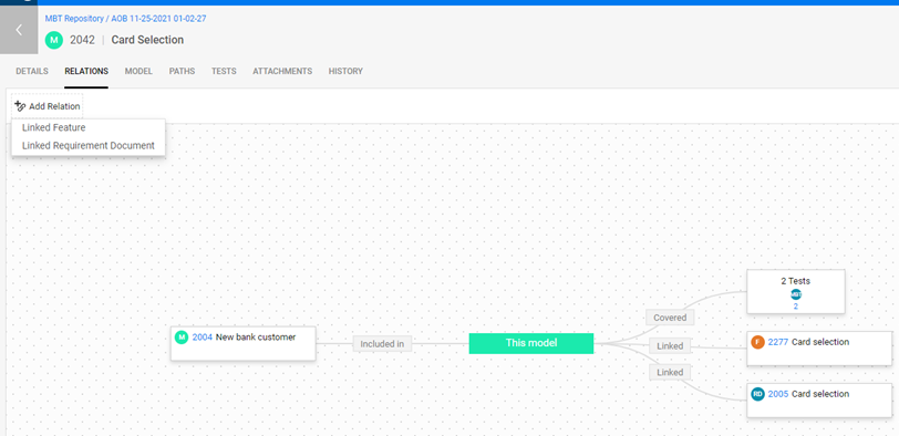
Example: In this example, the model Card selection is a sub-model in the New bank customer model. It is covered by two tests, and it is related to one feature and one requirement.
Modify a model's details and phases
You can add the following details to your model:
-
In the Details tab you can define further information such as adding tags to a model, assigning a model to your My Work area, or working with custom fields. For details, see Basics.
-
In the upper right corner of the screen, set the Model's Phase. MBT uses phases to represent the current state of an item. As you work on items, advance them from phase to phase. When you set a model's phase to Ready, the icon representing the model changes color from gray to blue. For details, see Phases.
Viewing a unit's summary
Unit cards display summary information in the context of the models and testing paths.
-
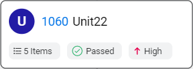
In the Models tab, unit cards include details on related backlog items, latest execution results, and risk. Tooltips show additional information where relevant.
-
In the Paths tab, units in the Path Preview pane display information related to your strategy. If you select the Agile Based strategy, you see details on related items. If you select Unit Recent Failure strategy, you see latest run results.
 See also: